
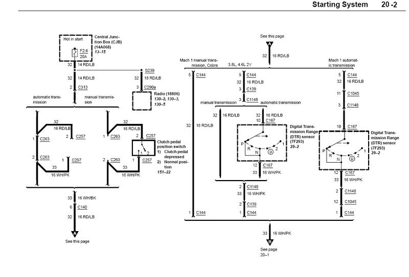
Here is the wiring diagram for what you want.
Results 31 to 40 of 57
-
10-05-08, 12:06 AM #31Senior Member


- Join Date
- Nov 2007
- Location
- Gilbert
- Posts
- 726
 ~Andrew
-
10-05-08, 12:08 AM #32Administrator

- Join Date
- Dec 2005
- Location
- Pittsburgh, PA
- Posts
- 8,632
This is how I have it hooked now. Originally Posted by IMSHAKN

The clutch switch just to the left of the gas pedal.
I believe this switch turns off the cruise control if you press in the clutch correct?
My concern is this switch is activated close to the top of the pedal. So the car would initially start to move when the spark is being pulled.
The CPP switch would disengage much lower during the pedal travel.
Not sure if it matters.
Sold
2004 Cobra, Whipple ,TH-400
Burning Corn
9.97 - 135.5
-
10-05-08, 12:12 AM #33Administrator
- Join Date
- Dec 2005
- Location
- Pittsburgh, PA
- Posts
- 8,632
You can't tap the CPP switch as it is only a 5 volt source. That is why MM&FF used the additional connector in the CPP to complete the ground.
Clutch Pedal Position Switch
The clutch pedal position (CPP) switch (Figure 27) is an input to the PCM indicating the clutch pedal position and, in some manual transmission applications, both the clutch pedal engagement position and the gear shift position. The PCM provides a 5-volt reference (VREF) signal to the CPP switch and/or a park/neutral position (PNP) switch (on the CPP signal line). If the CPP switch (either or both CPP and PNP switches are closed) is closed, indicating the clutch pedal is engaged and the shift lever is in the NEUTRAL position, the output voltage (5 volts) from the PCM is grounded through the signal return line to the PCM, and there is 1 volt or less. One volt or less indicates there is a reduced load on the engine. If the CPP switch (or PNP switch on vehicle or both CPP and PNP switches open on the vehicle) is open, meaning the clutch pedal is disengaged (all systems) and the shift lever is not in NEUTRAL position (PNP switch systems), the input on the CPP signal to the PCM will be approximately 5 volts. Then, the 5-volt signal input at the PCM will indicate a load on the engine. The PCM uses the load information in mass air flow and fuel calculations.Sold
2004 Cobra, Whipple ,TH-400
Burning Corn
9.97 - 135.5
-
10-05-08, 12:20 AM #34Administrator
- Join Date
- Dec 2005
- Location
- Pittsburgh, PA
- Posts
- 8,632
The MSD unit has two wires to activate the system. I am using the 12V source wire.
The article in MM&FF is using the Ground Wire utilizing the CPP switch.Sold
2004 Cobra, Whipple ,TH-400
Burning Corn
9.97 - 135.5
-
10-05-08, 12:21 AM #35Senior Member
- Join Date
- Nov 2007
- Location
- Gilbert
- Posts
- 726
Correct on the wire. Personally I would think it would be better to have it hooked up as you do unless you only want it activated at the floor, in which case you'd want it on the red/blue wire as shown on the link you found from that website as that will be a complete circuit at full disengagement of the clutch. I don't know about you, but I don't launch with the pedal to the floor...maybe I'm interpreting it wrong but I think you've got it hooked up the better way.
~Andrew
-
10-05-08, 12:24 AM #36Senior Member
- Join Date
- Nov 2007
- Location
- Gilbert
- Posts
- 726
Think of it this way, it works perfectly the way you've got it now and even if it's still pulling spark for the extra split second that it takes for the pedal to travel up breaking the circuit you are not going to see much of a difference...or am I missing something about this second wire they are using to hook it up? Half the time I think those guys in the magazine articles are on crack so I wouldn't assume their way is necessarily best...your way makes more sense to me.
~Andrew
-
10-05-08, 12:25 AM #37Administrator
- Join Date
- Dec 2005
- Location
- Pittsburgh, PA
- Posts
- 8,632
I found a better diagram and added it to your post.
My clutch engages closer to the floor.
CPP is about an 1 1/2" off the floor.Sold
2004 Cobra, Whipple ,TH-400
Burning Corn
9.97 - 135.5
-
10-05-08, 12:29 AM #38Senior Member
- Join Date
- Nov 2007
- Location
- Gilbert
- Posts
- 726
Lol. much better version of my diagram...I don't like pressing my book too hard against the scanner as the bindings for uses on this book and the factory service manual are not the best. Then again they invented live chat for a reason.
 ~Andrew
-
10-05-08, 10:20 PM #39Administrator
- Join Date
- Dec 2005
- Location
- Pittsburgh, PA
- Posts
- 8,632
I did a little testing tonight and the MSD works great. I am going to test it at the track the way I currently have it setup activated by the clutch cruise control kill switch. Originally Posted by IMSHAKN
I did a little more thinking about how it works. My concern was when I hit the slicks at 6000 RPM the two step would be activated until the clutch pedal was just about all the way out.
In my mind I could see a bad launch and 60 ft time due to hitting the tires with spark being pulled too long.
Then I thought a little more. When I launch my shift light comes on well after launch at 6000 RPMs. So the motor is losing RPM as the clutch engages and the tires hook which would deactivate the MSD being the RPMS are below the selected setting. So even though the electrical deactivation is at the top of the pedal the loss of some RPM as things hookup will also deactivate the MSD.Sold
2004 Cobra, Whipple ,TH-400
Burning Corn
9.97 - 135.5
-
10-05-08, 10:37 PM #40Senior Member
- Join Date
- Nov 2007
- Location
- Gilbert
- Posts
- 726
Personally I would think it would give you a more consistent 60 as you'd still have plenty of grip and you are not going to exceed your launch RPMs until probably well after you completely drop the clutch as you will see a bit of that drop in RPM. I say try it and we can watch what it's doing on camera...assuming your camera man knows how to use the thing. Originally Posted by BurnTire
~Andrew

 Reply With Quote